The Keyboard
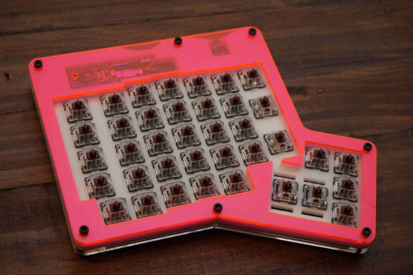
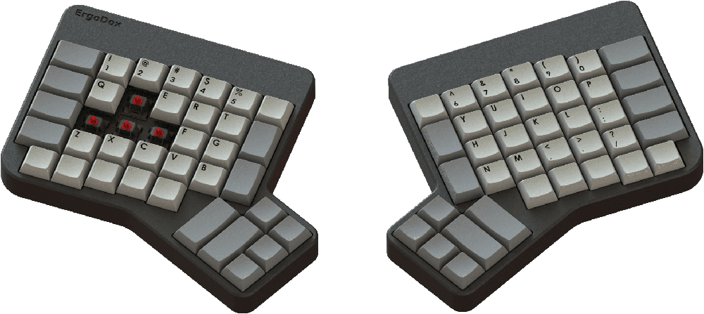
Ergodox is a keyboard project designed with ergonomics in mind, available either as a DIY kit or an assembled, commercial version. It uses 76–80 Cherry MX style mechanical switches (such as Cherry or Gateron) laid out in a columnar stagger (rather than the more conventional row stagger) layout with components that can easily be sourced. The keyboard is completely programmable and can be flashed with several different firmware options.
The entire project (including this website) is open source, allowing you the freedom to modify and tweak the project as you see fit.
Assembling this project will require some patience, soldering ability, and access to a computer to flash the firmware onto the keyboard.
Who built this?
The ErgoDox project is the result of many real, human contributors:
- Dominic Beauchamp (“Dox”): Original developer, inspired by the Key64 Keyboard.
- Fredrik Atmer (“bpiphany”): Designer of the printed circuit board (PCB).
- Litster: Designer of the popular layered acrylic case.
- Ben Blazak: Author of the original firmware.
- Erez Zukerman, Dmitry Slepov, and Yaara Lancet: Founders of the ErgoDox EZ.
- Jack Humbert: Creator of QMK Firmware, based on TMK.
- Max Whittingham (“robotmaxtron”): Creator of this documentation hub.
- …and lots of others have contributed to the project in various ways.
Contributing
Contributions to the documentation and build guides are welcome! If you want to contribute, pull requests and bug reports can be filed at our GitHub repository.
License
The keyboard design and hardware files are licensed under the GNU Public License 3. This website and its content are licensed under the MIT License. GeekHack Thread
Guide
Choosing a Layout
Before sourcing parts, you’ll need to decide on a layout:
- Standard 76-key: The original ErgoDox layout.
- 80-key layout: Adds four additional 1u keys to the inner columns.
Required Tools
To assemble the ErgoDox, you will need the following tools:
- Soldering Iron & Solder
- Flush Cutters (for trimming component legs)
- Wire Strippers (for USB cable wiring)
- Screwdriver (for case assembly)
Skills
The build guide assumes a basic understanding of soldering. If you’re new to soldering, we recommend watching a few tutorial videos on YouTube before starting.
Parts
A complete ErgoDox build requires sourcing the following components. Most parts are available from common electronics suppliers such as Mouser, Digikey, or through community group buys.
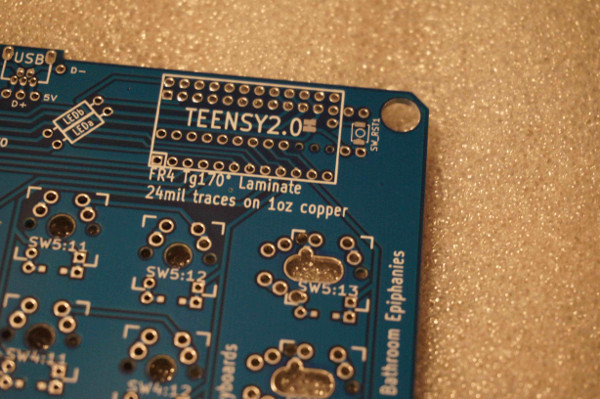
PCBs
PCBs can be ordered with files from the ErgoDox GitHub repo using the provided Gerber files. Common PCB manufacturers include OSHPark, Seeed Studio, and JLCPCB. Costs will vary depending on the quantity ordered, options chosen, etc. JLCPCB has historically had the lowest prices, and several users have had PCBs printed by them.
Vendors
- JLCPCB – Upload Gerber files to order PCBs
- JLC3DP - 3D Printed Case
- OSHPark - PCBs
- Latest Revision: https://oshpark.com/shared_projects/darvLWxS
- Seeed Studio
- Profet Keyboards
Electronics
The following electronic components are an example of the parts needed for a full build. To make sourcing easier, we’ve provided links to some vendors such as DigiKey and Adafruit for each part:
| Component | Qty | Part Number |
|---|---|---|
| Adafruit ItsyBitsy 32u4 - 5V 16MHz | 1 | 3677 |
| MCP23018 I/O Expander (DIP-28) | 1 | MCP23018-E/SP-ND |
| Cherry MX Compatible Switches | 76-80 | Kailh Brown |
| 1N4148 Diodes (Through-hole) | 76-80 | 1N4148FS-ND |
| 2.2kΩ Resistors | 2 | CF14JT2K20TR-ND |
| 0.1µF Ceramic Capacitor | 1 | BC2665CT-ND |
| 3mm LEDs | 3 | 1080-1041-ND |
| 220Ω Resistors | 3 | CF14JT220RCT-ND |
| 3.5mm TRRS Jacks | 2 | CP-43514-ND |
| TRRS Cable (Male-Male) | 1 | 5600-FE-25TRRS-02-MM-ND |
| Mini USB connector | 1 | WM17115-ND |
| Short Micro to Mini USB Cable | 1 | 839-10-00655-ND |
| Mini USB Cable | 1 | 2987-DH-20M50055-ND |
Case & Keycaps
There are several options for the ErgoDox case:
- Layered Acrylic: The most popular and affordable option. You can laser cut your own or buy a kit. Files are available in our GitHub Repo.
- 3D Printed: Files are available in our case repository.
- Custom Wood: Various artisans create high-end wooden cases.
Tenting
A tenting stand is also available for 3D printing to improve ergonomics when using the layered acrylic case.
Keycaps
You’ll need a set of Cherry MX-compatible keycaps. The exact number depends on your chosen layout:
| Layout | 1u Keys | 1.5u Keys | 2u Keys | Total |
|---|---|---|---|---|
| Standard (76 keys) | 60 | 12 | 4 | 76 |
| Expanded (80 keys) | 68 | 12 | 0 | 80 |
Assembly Guide
Assembling an ErgoDox is a rewarding experience, but it requires patience and attention to detail. This guide is organized into logical phases to help you through the process.
Before you begin, ensure you have all the necessary tools and parts ready.
Phase 1: Low-Profile Components (Diodes)
We start with the diodes, as they are the shortest components and easiest to solder first. Diodes are directional and must be oriented correctly.
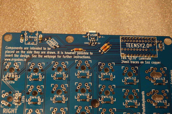
- Preparation: Flip both PCBs face down (this is the side without the white silkscreen markings for ICs and resistors).
- Placement (Either Method):
- Surface Mount (SMD): The small line on the diode must face the square copper pad.
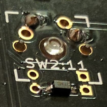
- Through-Hole (THT): Bend the legs and insert through the two holes next to the copper pads. The black line on the diode should match the line on the silkscreen (facing the square pad).
- Soldering: Solder all diodes on both PCBs and trim the legs if using through-hole.
Phase 2: Main ICs and Resistors
Now, flip the PCBs over to the top side (with the white silkscreen).
Left-Hand PCB: I/O Expander
- MCP23018 (DIP-28): Insert the chip into the PCB. Ensure the notch on the chip matches the notch on the silkscreen outline.
- Capacitor (Optional): Insert the 0.1µF ceramic capacitor into the
C1position. Bridge the two copper pads immediately to the left with a small piece of wire.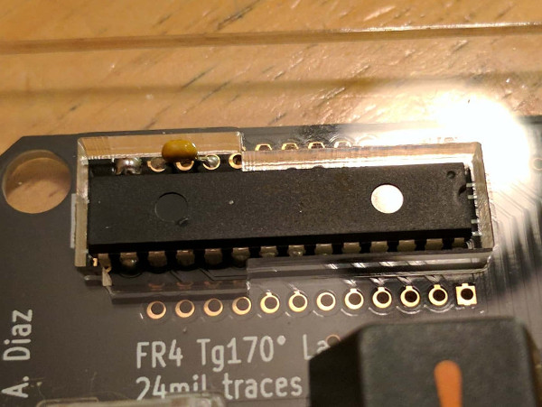
Right-Hand PCB: Resistors
Solder the following resistors into their designated spots:
- 2.2 kΩ Resistors: Typically labeled
R1andR2. - 220Ω Resistors: Typically labeled
R3,R4, andR5.
Phase 3: Connectors and Microcontroller
These taller components should be installed once the flatter electronics are in place.
-
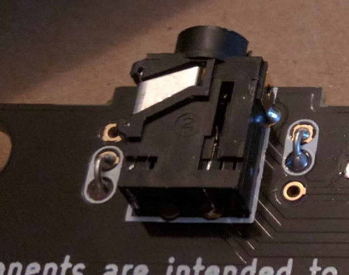
TRRS Jacks (Both Hands):
- Insert the 3.5mm TRRS jacks and solder.
- Bridge Jumper: Use jumper wires or clipped diode legs to bridge the white pairs of pads next to the jack as indicated. This is crucial for the two halves to communicate.
-
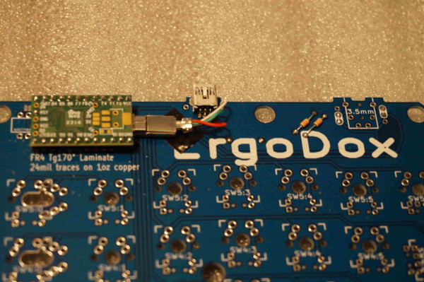
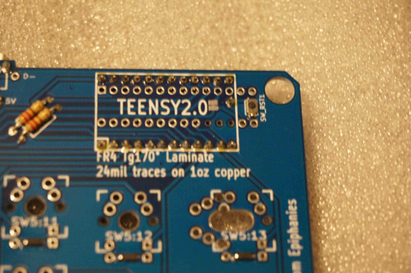
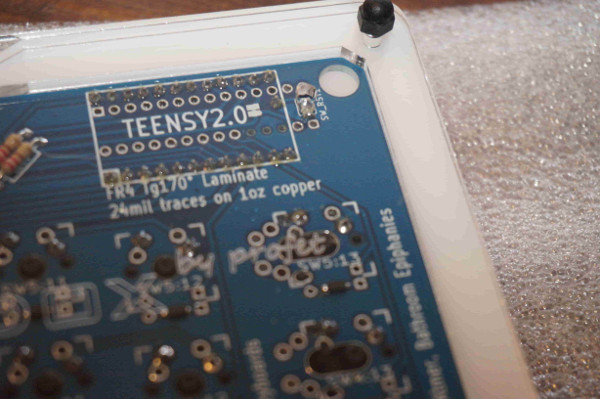
Microcontroller (Right Hand):
- Install male pins to the underside of the Adafruit ItsyBitsy.
- Solder it to the right-hand PCB with the USB port facing the resistors.
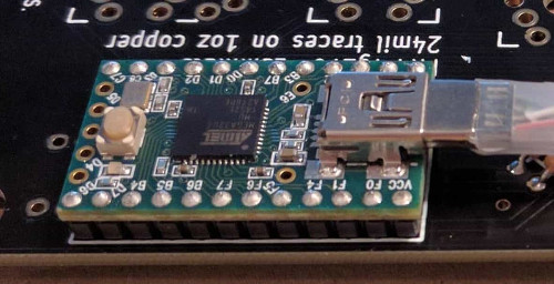
Phase 4: USB and Internal Wiring (Right Hand)
- USB Connector: Insert the mini USB connector into the right-hand PCB and solder securely. This will serve as
the external connection to your computer.
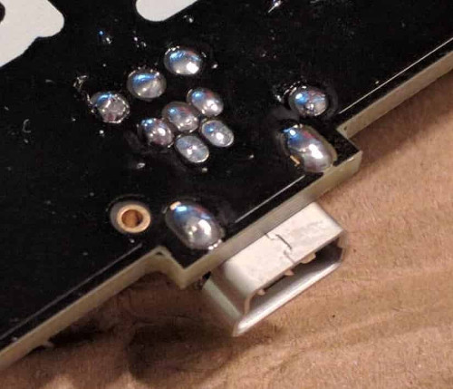
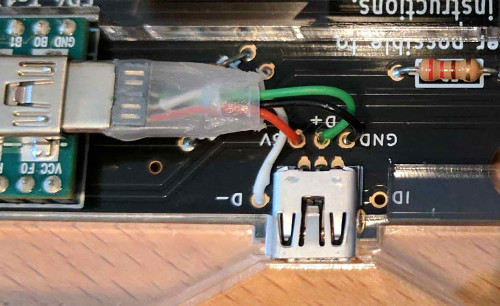
- Internal Wiring: If your case uses a pigtail, strip a micro USB cable and wire it to the PCB pads as follows:
| Wire Color | Function | PCB Pad |
|---|---|---|
| Red | 5V Power | 5V/VCC |
| White | Data - | D- |
| Green | Data + | D+ |
| Black | Ground | GND |
Phase 5: Switches, LEDs, and Final Case Assembly
-
Switches:
- Place the switch plate (if using one) over the PCB.
- Insert the Cherry MX switches through the plate and into the PCB.
- Ensure all pins extend through the holes without bending.
- Solder all switches on both halves.
-
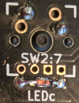
LEDs (Right Hand Only):
- Insert 3 mm LEDs through the switch housings on the right-hand PCB.
- Polarity: The shorter leg (negative) must go into the square hole. Solder and trim the excess legs.
-
Final Polish:
- Complete the case assembly using screws and standoffs.
- Connect the two halves using a TRRS cable.
- ⚠️ CRITICAL: NEVER connect or disconnect the TRRS cable while the keyboard is plugged into your computer. This can cause a short and cause permanent damage to the I/O expander!
Other Assembly Guides
External links to some popular guides to building the ErgoDox Keyboard:
- YouTube Build Guide: There are several other good video guides available on YouTube.
- Imgur Build Log: User robotmaxtron shares his build log (including mistakes).
Firmware
The ErgoDox supports several firmware options. Choose the one that best fits your needs. The main controller has traditionally used an ATmega32u4 breakout board.
QMK Firmware
The most popular and recommended firmware. It offers powerful features like layers, macros, and deep customization.
- QMK Homepage
- GitHub Repository
- Configuration Tool: Use the ErgoDox-EZ Configurator to generate keymaps and hex files easily.
Other Options
- Experimental v3 ErgoDox Firmware: Modernized fork of Ben’s original firmware with some additional features.
- TMK Firmware: Oleg Kostyuk (cub-uanic) ported the TMK firmware (written by “hasu”) to the ErgoDox! A lightweight, feature-rich firmware.
- Original Firmware: Ben Blazak’s original code. GitHub.
Flashing Instructions
Once you have your firmware file (.hex), follow these steps to flash it to the Adafruit ItsyBitsy:
- Enter Bootloader: Press the reset button on the ItsyBitsy twice in quick succession.
- Flash Code: Use
avrdudeor the Arduino IDE to upload the firmware. - Verify: The keyboard should automatically reset and be ready for use.
Variants
The ErgoDox project has inspired several popular variants and derivatives. While they share the core columnar stagger design, they each offer unique improvements such as pre-assembled convenience, concave key wells, or enhanced connectivity.
On the following sections, we’ll explore some notable ErgoDox variations:
- ErgoDox EZ: A popular pre-assembled, commercial version.
- ErgoDox Infinity: A high-tech version with LCD screens and USB-C.
- Dactyl: A 3D-curved, concave variant for maximum ergonomics.
- Kinesis Advantage 360: A commercially available variant with a 3D-curved layout that can be customized with ZMK.
ErgoDox EZ
The ErgoDox EZ is a commercially assembled version of the ErgoDox, available with a 2-year warranty and fully customizable layout.
Configuring the EZ
The ErgoDox EZ can be configured using the Oryx Configurator without writing any code. It also supports flashing custom QMK firmware for power users.
ErgoDox Infinity
The ErgoDox Infinity was introduced as a high-tech variant of the ErgoDox and originally sold by Input Club. It introduced several modern enhancements to the original design.
Key Features
- USB-C Connectivity: Modern, reversible ports for better reliability.
- Integrated LCD Screen: Displays current layers, statistics, and more.
- Independent Halves: Each half can function as a standalone keyboard.
- Kiibohd Firmware: Runs on the specialized Kiibohd controller software.
Configuration
The Infinity can be configured using the Kiibohd Configurator or by directly modifying the Kiibohd firmware source code.
Sourcing Materials
-
Build Guides:
-
Firmware options:
-
Cases:
-
Printed Circuit Board:
-
Pre-built Options:
Dactyl
The Dactyl is a split-hand, concave, columnar keyboard designed by Matthew Adereth. It is a highly ergonomic variation of the ErgoDox design.
Key Differences
- Concave Mounting: Switches are mounted in a 3D-curved “well” for better ergonomics.
- 70-Key Layout: Removes the inner column of keys compared to the standard ErgoDox.
- 1u Outer Column: Uses 1u keys instead of the standard 1.5u.
- Hand-wired: Typically built without a PCB, though flexible PCB options exist.
Resources
As a Gamepad
Custom Layouts
The ErgoDox is popular for gaming thanks to its split design. Many users use only the left half as a high-end gamepad, custom-tailored with specific layers for MMOs or FPS games.
Gallery